Thursday, April 24, 2014

Thread Cutting in Bolt & Nut-Autodesk Inventor 2013 (with caption and audio narration)

Thread Cutting in Bolt

Thread Cutting in Nut

Serial No. 205

Thread Cutting in Bolt & Nut-Autodesk Inventor 2013 (with caption and audio narration)

In this video tutorial we will show how to create a thread on a nut and bolt by using a thread profile and applying the coil tool in Autodesk Inventor. In our previous video we displayed how to create a sketch profile of a Unified and American screw (internal). We will utilize the same sketch profile here.


download-Link


Click the following link to get the model file: - http://bit.ly/2nI85Pq


 Transcription of Video

  1. Open the file of Bolt.
  2. Start a new sketch on YZ plane of the part.
  3. Activate the Slice Graphics Command.
  4. This will slice away the portion of the model temporarily that hides the plane on which we want to sketch.
  5. Take the project of the model by activating the Project Cut Edges tool and convert them to the construction geometry.
  6. Now draw a rectangle as shown and apply a construction override on it.
  7. Open the file named Unified and American screw external thread.
  8. Select the sketch profile drawn in the file and copy it as displayed.
  9. Switch back to the Bolt file and paste it on the sketch.
  10. Add a line to close this profile.
  11. Rotate this profile 90° in a clockwise direction by utilizing the Rotate Tool.
  12. Pick up the Move tool and place the profile on a new location.
  13. Snap it to this point of rectangle.
  14. Finish the sketch and activate the coil tool, it will automatically select the thread profile.
  15. Next define the Z axis of the model as the Axis for the thread cutting.
  16. Switch to Coil Tab of the tool dialogue box and set the type of the coil to Pitch and Height.
  17. Fill the values in the Pitch and Height input boxes.
  18. Switch back to the Coil Shape Tab and Select the Operation Type to Cut.
  19. Click Ok to execute the command.
  20. Start a new sketch over YZ Plane.
  21. Take the project of the constructed part and take the measurement between the two threads to check the pitch created by coil tool.
  22. Exit from the sketch and close its visibility from the browser bar.
  23. Save the file and close it.
  24. Open the file of Nut.
  25. Start a new sketch over the back face of the model.
  26. Select the projected centre point of the model and convert it to centre point.
  27. Exit the sketch and activate the hole tool.
  28. It will automatically select the placement point of the hole because we applied a centre point override over the projected centre point of the part in our previous sketch.
  29. Set the type of the hole to Tapped Hole.
  30. Define the setting of the hole as displayed and execute the command.
  31. Check the diameter of the hole by utilizing the measure tool.
  32. Now select the hole feature in the browse and edit it.
  33. Set the type of the hole to simple hole and execute the command.
  34. Activate the chamfer tool.
  35. Set the type of the chamfer to distance and angle.
  36. First select the back face from which the chamfer is angled and then select this edge of the hole.
  37. Fill the values in distance input box and leave the default angle value unchanged.
  38. Click Ok to execute the command.
  39. Start a new sketch over YZ Plane.
  40. Activate the slice graphics command and the project of the model edges.
  41. Convert all the lines into construction line.
  42. Open the file named Unified and American screw external thread.
  43. Select the sketch profile drawn in the file and copy it as displayed.
  44. Switch back to the Nut file and paste it into the sketch.
  45. Add a line to close this profile.
  46. Rotate this profile 90° in a clockwise direction by utilizing the Rotate Tool.
  47. Now draw a rectangle as shown and apply a construction override on it.
  48. Pick up the Move tool and place the profile on a new location.
  49. Measure the length of the Nut.
  50. Activate the coil tool from the right click context menu, it will automatically select the thread profile.
  51. Next define the Z axis of the model as the Axis for the thread cutting.
  52. Switch to Coil Tab of the tool dialogue box and set the type of the coil to Pitch and Height.
  53. Fill the values in the Pitch and Height input boxes.
  54. Switch back to the Coil Shape Tab and Select the Operation Type to Cut. Next execute the command.
  55. Start a new sketch over YZ Plane.
  56. Take the project of the constructed part and take the measurement between the two threads to check the pitch created by coil tool.
  57. Exit from the sketch and close its visibility from the browser bar.
  58. Save the file.

Monday, April 14, 2014

Hem Tool-Autodesk Inventor 2013 (with caption and audio narration)

Hem Tool

Serial No. 204

Hem Tool-Autodesk Inventor 2013 (with caption and audio narration)

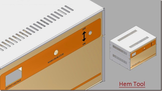
Hem tool is used to strengthen or eliminate sharp edges of the sheet metal face. You can create single, double, rolled and teardrop hems. This tool is available on Create panel of sheet metal Tab.

download-Link 


Click the following link to get the model file: - http://bit.ly/2nJxFnj 


 Transcription of Video

1. Open the Assembly file of ‘Chassis for Constant Voltage Transformer’.

2. In the Browser Bar double click the ‘Part3' file to edit it.

3. Go to the ribbon, Create panel > Hem tool.

4. The Hem dialogue box is visible in the design window.

5. In the Shape tab, the Edge Selection button is active.

6. Select the left inside vertical edge of the sheet.

7. The preview of Hem is displayed in the design window.

8. Fill the values in the ‘Gap’ and ‘Length’ input box as displayed.

9. Click OK to create new hem.

10. Return back to the assembly environment.

11. Mirror of Part3 is automatically updated.

12. In the Browser Bar, double click the ‘Part4' file to edit it.

13. Repeat the same steps and apply two more hem features on the left and right inside vertical edges of the sheet.

14. Reactivate the hem tool and select top inside edge of the sheet.

15. Click more button to expand the dialogue box.

16. By default, ‘Width Extents’ Type ‘Edge’ is selected.

17. Change it to ‘Offset’.

18. In the ‘OffSet1’ input box, expand the node to activate the Measure tool.

19. Select the left face of the sheet and right face of the hem.

20. The distance between the two faces will be added in the offset input box.

21. In the similar way add values in the ‘OffSet2’ input box.

22. Switch to the Bend tab, change the ‘Relief Shape’ type to ‘Tear’.

23. Click OK to execute the command.

24. At the end, remove the remaining extended faces by using Cut tool.

25. Open the Part4 file separately, to check the Flat Pattern of the sheet.

Sunday, April 13, 2014

Face tool and Flange tool-Autodesk Inventor 2013 (with caption and audio narration)

Face tool and Flange tool

Serial No. 203

Face tool and Flange tool-Autodesk Inventor 2013 (with caption and audio narration)

download-Link 


Click the following link to get the model file: - http://bit.ly/2mVWsV4


Transcription of Video

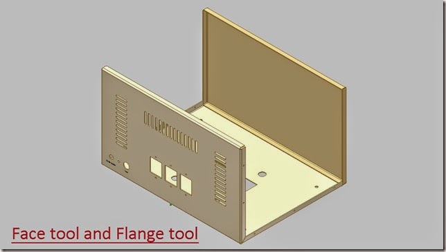
Face Tool is used to create sheet metal faces by utilizing a closed sketch profile. It is similar to extrude tool where height is automatically set to the thickness of the sheet. This tool is available on the Create panel of Sheet Metal Tab.

1. Open the Assembly file of ‘Chassis for Constant Voltage Transformer’.

2. In the Browser Bar double click the Part2 file to edit it.

3. A closed sketch profile is previously created in Sketch1 of this file.

4. Go on the ribbon, Create panel > Face tool.

5. The Face dialogue box is visible in the design window.

6. The rectangular profile is automatically selected in the design window.

7. Click the ‘Flip Offset’ button to change the direction of the extrusion.

8. And click OK to create sheet metal face.

Flange Tool is used to add a sheet metal planer face and a bend on an existing sheet metal edge. The depth and the angle of the flange can be specified. This tool is available on the Create panel of Sheet Metal Tab.

1. Rotate the model by using View Cube.

2. Go on the ribbon, Create panel > Flange tool.

3. The Flange dialogue box is visible in the design window.

4. In the Shape tab there are two options for creating a flange, first option is ‘Edge Select Mode’ and the other is ‘Loop Select Mode’.

5. Currently the Edge Select Mode button is active allowing you to select only one edge at a time.

6. Select four inside edges of the sheet one by one.

7. Delete the selections and try next option.

8. Click the ‘Loop Select Mode’ button, so you can select multiple edges at a time.

9. By default, ‘Inside of bend face’ option is selected as the ‘Bend Position’.

10. Change it to ‘Outside of base face’.

11. Fill the value in the Height Extents field.

12. Click OK to create new flange.

Punch Tool-Autodesk Inventor 2013 (with caption and audio narration)

Punch Tool

Serial No. 202

Punch Tool-Autodesk Inventor 2013 (with caption and audio narration)

The Punch Tool command is used to cut or deform sheets by placing predefined Punch tool geometry. To apply this tool the sheet metal face must have a sketch with one or more unconsumed centre mark. This tool is available on the Modify panel of Sheet Metal Tab.


download-Link 


Click the following link to get the model file: - http://bit.ly/2onIxY5


 Transcription of Video

    1. Open the Part 1 file.

    2. Start a sketch on the back face of the model to define centre marks for punch tool.

    3. Place a centre point on the sheet and apply dimensions as displayed.

    4. Duplicate this point 4 times by using Rectangular Pattern tool.

    5. Activate the tool and select the centre point.

    6. Define the direction of Pattern.

    7. Fill up the occurrence count and spacing between the points.

    8. Apply the command.

    9. Exit from the sketching mode.

    10. Activate the Punch tool from the Modify panel.

    11. The PunchTool Directory dialogue box is displayed.

    12. Manually locate Sheet Metal Punch iFeature file LouvrePunch and open it.

    13. Punch Tool dialogue box is displayed and a preview of punche is visible.

    14. Switch to Geometry tab and fill the value in the Angle field.

    15. Next click the Size tab and change the values of Width, Length and Height one by one.

    16. Click the Refresh button to update all the added values on-screen.

    17. Click Finish in the Punch Tool dialog box to place the punches.

Thursday, April 10, 2014

Chassis for Constant Voltage Transformer by Sheet Metal (Autodesk Inventor 2013)

Chassis for Constant Voltage Transformer by Sheet Metal

Serial No. 190

Chassis for Constant Voltage Transformer by Sheet Metal (Autodesk Inventor 2013)

Inside this video, viewers will watch full detailed process of creating this model through Autodesk Inventor Software's Sheet Metal design functionality.

download-Link 

Click the following link to get the model file: - http://bit.ly/2nD4jH4

Creating Relation Based Sketches in Creo Parametric 2.0 || British Standard Pipe Thread Profile

BSP Pipe Thread


This tutorial will display how to create relation based sketches in Creo Parametric. As an example we will create a sketch profile of a British Standard Pipe Thread. The pitch of the profile is 1/14 inch.


Transcription of Video

  1. Start a new part file from scratch with the default template and give it a name ‘BSP_Thread_Profile.
  2. You can see the English template is opened by default.
  3. Select the Front Datum plane and create a new sketch on this plane.
  4. Click the Sketch View icon to orient the sketching plane parallel to the screen.
  5. Clear the screen by closing the visibility of Spin centre, Datum Planes, Axis, Points etc.
  6. Go to setup panel and define the Grid settings.
  7. In the Grid setting dialogue box activate Static Grid spacing option and modify the X and Y spacing as displayed.
  8. Open the visibility of Grid from Sketcher display filters.
  9. Now zoom the window quite considerable to view the Grid.
  10. Draw a sketch with the help of line tool as displayed.
  11. You will see that some constraints are automatically applied and intimated time to time by the software.
  12. Create a centreline for our sketch.
  13. Apply dimensions related to our profile specification.
  14. Lock this dimension to preserve it from any modification.
  15. Again, apply an angular dimension.
  16. Apply constraints according to the demand of the sketch.
  17. Quit the sketching mode.
  18. Switch to Annotate Tab.
  19. Activate Show Annotation Tool and select the sketch.
  20. All the applied dimensions in the sketching environment will be visible.
  21. Terminate the command.
  22. Select this dimension in the design window that will be highlighted in Model Tree.
  23. Open its property from the context menu.
  24. Change its display name to ‘P’ and apply changes.
  25. Go to model Tab—Model Intent Panel and expand it to find Switch Symbol Command.
  26. Click it to display names of dimension in spite of values.
  27. Re-edit the sketch.
  28. Draw an arc tangent to both the lines.
  29. Define the Angular dimension and apply a Lock over this dimension.
  30. Exit the sketching mode and again redefine the names of the dimensions.
  31. Remove the Prefix otherwise dimension will display Rr name that will be very confusing.
  32. Expand the Model Intent Panel and Activate the Relation command.
  33. Start adding the values according to the profile. You can type or paste the values.
  34. Execute and verify the relations.
  35. Select the dimension of pitch with the help of selection filters easily.
  36. Move it to new location.
  37. Re-edit the sketch.
  38. Add more dimensions to the sketch and change its name.
  39. Give away relation according to the profile.
  40. Adding this dimension is conflicting with a previously placed constraint, so remove that constraint.
  41. Similar operations are being performed as done earlier.
  42. Again re-edit the sketch.
  43. Select these two lines and convert them to construction lines.
  44. Complete the sketch by adding few more arcs and lines.
  45. Select these sketches and duplicate using Mirror Tool.
  46. Now sketch is complete so finish the sketch and save the file.
  47. If you change the pitch, the profile will change simultaneously.